Azimuthal Projection: Orthographic, Stereographic and Gnomonic
The azimuthal projection plots the surface of the Earth using a flat plane.
Imagine light rays radiating from a source following straight lines. Those light rays intercept the globe onto a plane at various angles.
The light source can be emitted from different positions developing different azimuthal map projections.
Some of the common perspective azimuthal projections include gnomonic, stereographic, and orthographic. Let’s look at the azimuthal projection in more detail.
Orthographic Projection
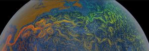
Here’s what the Earth would look like if you were thousands of miles away in space. Orthographic maps are common for inset maps as it’s the one azimuthal projection people can commonly relate to for perspective.
The Orthographic projection geometrically projects the globe onto a plane with the point of projection as infinity. All the projection lines are orthogonal to the projection plane.
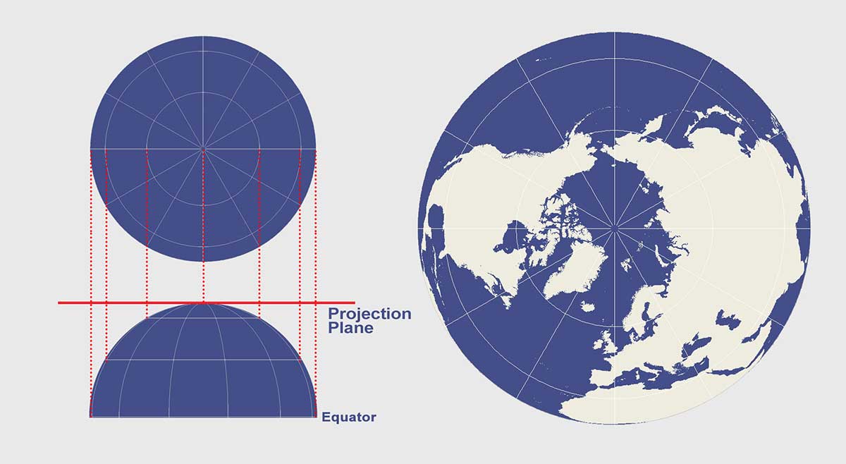
Orthographic Map Distortion
The orthographic projection distorts shape and area near edges due to perspective.
Directions are true from the point of projection, with scale defeating away from its radiating lines.
The orthographic projection isn’t conformal nor equal area.
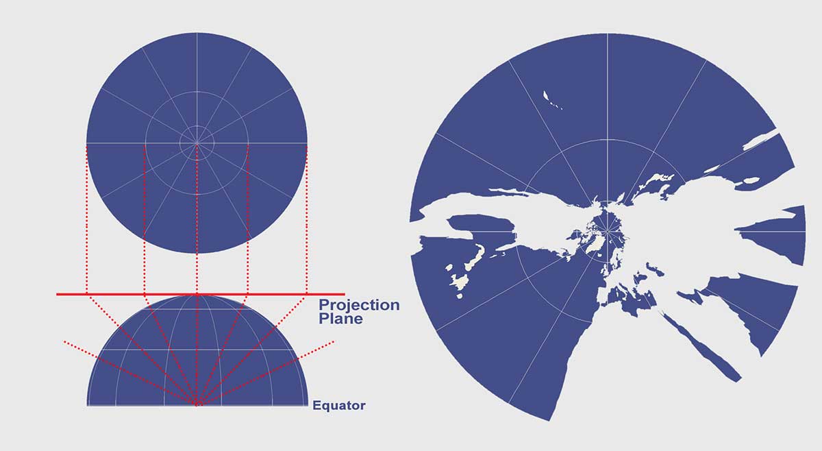
Stereographic Projection
The key to understanding the stereographic projection is understanding its source of light. At the opposite end where the tangent plane touches the reference globe is the light source for the stereographic projection.
This map projection is commonly used for polar aspects and navigation maps because of how it preserves shapes (conformal). Despite how the scale is greatly stretched by perspective, it’s been used to map large continents or oceans including the Arctic and Antarctic.
Stereographic Map Properties
In terms of map distortion, the stereographic projection is conformal but the distortion of area and distance increases away from the center point of projection.
Direction is true from the center point with each straight line representing a great circle. The stereographic projection isn’t equal in area nor equidistant.
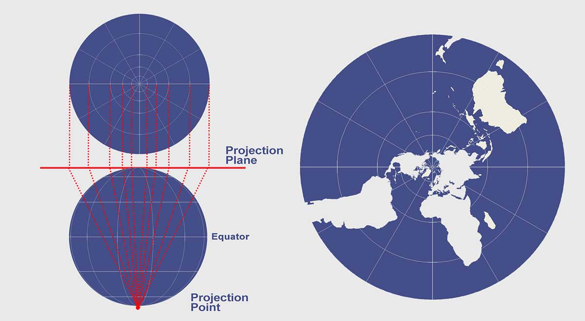
Gnomonic Projection
Unlike the stereographic projection, the Gnomonic projection light source is located at the sphere center. This means that it can only present less than one hemisphere at a time.
Each great circle (geodesic) including meridians is mapped to a straight line. This makes the gnomonic projection easiest to plot out the shortest route. This is why navigators have used the gnomonic projection along with Mercator maps (cylindrical projections) for finding the shortest route between two points. Furthermore, seismologists use this map projection because seismic waves often travel down great circles.
Thales first introduced the Gnomonic projection in the 6th century BC and is one of the oldest map projections today.
Gnomonic Projection Distortion
The Gnomonic projection isn’t equal area, equidistant, or conformal as the distortion of these two properties increases away from the center point.
You should avoid using the Gnomonic projection for measuring distances. However, it’s particularly useful for navigation as a straight line drawn on the map is a great circle (geodesic).
Azimuthal Projection Advantages and Disadvantages
The azimuthal projection intercepts the Earth according to the laws of perspective and plots the traces of light onto a developable surface. When the source of light is placed in different locations, it affects the geometry of the projection.
When polar (normal) projections are the center point of the planar projection surface, it results in meridians as radial straight lines converging at poles. This means that azimuthal projections present true direction (azimuth) from the mapmaker’s center point of choice. Further to this, a property of azimuthal projections is that they have straight geodesics through the map center. This makes azimuthal projections well-suited for maps of the Arctic, Antarctic, and hemisphere types of maps.
Whether the plane is tangent (just touching it) or is secant (intersecting it), you can minimize the level of choosing standard lines. The tangent plane has one point of contact (a point of tangency), whereas the secant plane has an entire line of intersection. A secant plane for a polar projection results in a latitude line as a standard line without any distortion. As a result, distortion increases away from the point of tangency or secancy.
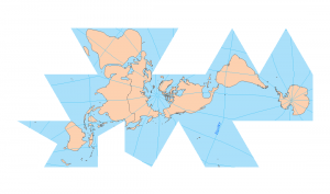
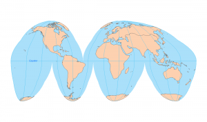
None of the perspective azimuthal projections can plot out the Earth as a whole, though a non-perspective azimuthal projection can.

I need a step by step description with diagrams on how the spherical earth will be projected on a plane surface or map with a source rays of light, using Orthographic, Stereographic and Gnomonic projections.
Good explanations. Thank you.
Hello! I was always wondering why both sets (orthographic, stereographic, gnomic) and (azimuthal, conical, cylindrical) are called PROJECTIONS.
They represent different things, and IMO the first makes more sense to be called a projection, since it’s about projecting the imagined light rays in a specific way.
Idk, is the second set actually called something like “projection planes”?
Your article is very well explained, but it also names both sets “projections”.
I’m really confused about that, and would be thankful if you could enlighten me regarding the proper semantics!
Thanks!